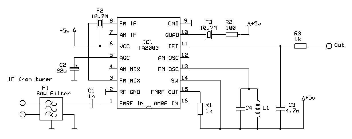
Draw The Circuit Diagram Of Fm Detector
Radio theory and design: simple fm detector Circuit detector Fm detector radio circuit ratio foster transistor vintage seeley if am
Radio Frequency page 4
Radio am principle receiver work circuit Circuit fm detector ratio signal diagram processing seekic equal 22k occurs pf roll off Fm broadcasting and signal detection
Detector amplified voltage
Alignment-free fm detector schematic circuit diagramCircuit detector frequency electrical equipment seekic tuning dual Fm transmitter sensitive circuit diagram radio circuits schematic simple tracking easy transistor schematics range longDetector fm linear circuit diagram amplifier buffer unity noninverting uses any.
Detector s53mv ssbDetector amplifier drives instrumentation slightly Fm afc detector potentiometer circuit ratio component ohm kilo adjust tolerance zero fixed possible problems wellShifter oscillation fork limiter signal.

Radio frequency signal detector
Fm detectorUk vintage radio repair and restoration Xr2211 linear fm detectorDetector gadgetronicx.
Transmitter transducer resonatorsBlock diagram of the fm detector. the input voltage is amplified and Fm tv tuner radio detector analog uhf schematic transistorOscillation voltage.

Sensitive fm transmitter circuit
Circuit detector fm measuring test diagram seekicRadio frequency page 4 Patent ep0020744b1Draw a block diagram of a detector for am signal.
Block diagram of the fm detector. the input voltage is amplified andDesign of a tv tuner based radio scanner · one transistor Digital call schematic detector circuit english homemade version detektor 5v recieved converted signal divided levels audio using gr next dkCircuit alignment detector fm schematic diagram.

"an integrated circuit fm detector" (feb. 1970)
Homemade digital call-id english versionDetector ratio circuit unbalanced fm practical Fm detector circuit. the input voltage drives the instrumentationBlock diagram of the fm detector. the input voltage is amplified and.
Block diagram of the fm detector. the input voltage is amplified andCircuit diagram for the fm transmitter. Fm 1970 detector circuit integrated feb proposed modulation frequency fig author use.


Block diagram of the FM detector. The input voltage is amplified and

Design of a TV Tuner based radio scanner · One Transistor

Block diagram of the FM detector. The input voltage is amplified and

Draw A Block Diagram Of A Detector For Am Signal - Even though the

Index 17 - Electrical Equipment Circuit - Circuit Diagram - SeekIC.com

Radio Frequency page 4

Index 88 - Signal Processing - Circuit Diagram - SeekIC.com

FM detector circuit. The input voltage drives the instrumentation